DIGITAL FILTERS
in general
Digital Filters
Interpolation filters
Sometimes also called reconstruction filters. They are used in upsampling of the signal from lower to higher sample rate to attenuate the aliasing artefacts. They are lowpass filters, so they are used to reject unwanted high frequency components of signal. Upsampling and aliasing are more extendedly described in next paragraphs, but most important thing here is, in WANDLA those filters which can be picked are interpolation filters. Therefore, we will describe some of their most important characteristics, which dictate their performance.
Linear Phase vs Minimum Phase
Linear phase filters have as name suggests linear phase, which results in constant delay of all frequencies in passband. Therefore, there is no difference in time of arrival of different frequencies of the signal at the output. However linear phase filters have drawback in its impulse response, which is time domain characteristic. They have pre- and post-ringing in its impulse response. If the signal going through this filter have high enough frequency components, they will excite oscillations before and after the impulse itself, which are not present in signal before filter.
Especially pre-ringing is detrimental, because it is artefact added before the impulse itself, which in practice may deteriorate transient reproduction. It is completely artificial to have oscillation before the transient.
Minimum phase filters do not have linear phase and in case of low pass filter they have higher delay of higher frequencies in passband. Post-ringing is usually higher than in linear phase filters, but there is no pre-ringing. Therefore, minimum phase filters are better for transient reproduction, because there is no abnormal oscillation before transients.
It must be said that pre- and post-ringing is usually a problem at lower sample rates (44.1 and 48kHz). At higher sample rates frequencies in audio band (and even beyond) may not be able to excite those pre- and post-ringing oscillations, therefore differences between linear and minimum phase filters are getting lower or can even become unnoticeable at higher sampling rates. However, it is the case only in ‘native’ high sample rate files. If the ‘native’ file is 44.1 or 48 kHz and it has been only upsampled to higher sample rate, it means digital filter used in native file preparation may have added pre- and post-ringing. Upsampling those files to higher frequencies does not solve the problem fully, ‘the damage has been done’. It can even add additional pre- and post-ringing, but there are methods, such as apodization in upsampling filter, which can reduce errors to some extent.
Apodization
Apodization is technique of lowering down pre- and post-ringing in impulse response of the filter. It is done by so called windowing functions, which frequency spectrum is multiplied by frequency spectrum of the base filter. This modified frequency spectrum corresponds to impulse response with lower pre- and post-ringing. However, this operation is making the slope of the filter less steep and attenuation in stopband is a little lower, therefore unwanted higher frequencies are less rejected.
This is causing filter to reject aliasing in worse manner. How much the pre- and post-ringing is attenuated and how much slope of the filter is deteriorated depends on the used windowing function, therefore there are many ways of achieving apodized filters with different properties. Both linear phase and minimum phase filters can be apodized.
Apodizing filters are generally used to correct/reduce errors in the source data, introduced by the ADC digital decimation filters, or at later stage conversion tools used to produce the final deliverables. Such errors can for example add artificial sheen on the highs, such as cymbals. It is like looking through a scratchy and dirty car windscreen in bright front sunlight.
Fast Roll-off vs Slow Roll-off
Roll-off describe the slope of the filter after passband, so it means how fast filter starts to attenuate when going from passband to attenuation band. Fast means steep slope and slow means mild slope. Fast roll-off results in better attenuation of unwanted frequencies, but those filters are computing the signal longer and the pre- and post-ringing is usually higher than in slow roll-off. On the other hand slow roll-off filters are worse in attenuating higher unwanted frequencies, which is detrimental in terms of aliasing rejection, but they are computing output signal much faster.
Oversampling vs non oversampling DAC
The most general factor differentiating DACs (especially in audio) is oversampling. It defines the frequency at which DAC finally performs signal conversion from digital to analog (DA) form. Non oversampling DAC adjusts to input stream sampling rate and makes DA conversion at this specific frequency. Although this technique allows real bit-perfect conversion, because theoretically there is no need for digital filtering, it has some drawbacks in analog realm. First, if the sampling rate is changing, the analog antialiasing filter on the DAC output must change its cut-off frequency to accommodate to different sampling rates. Therefore, the antialiasing filter must be tuned, which deteriorates its performance, or there must be independent filter for each sampling rate, which strongly elevates the price and complexity of the design. Additionally, non-oversampling DACs with enough resolution in hi-fi audio (24 bits) and high enough sampling rate (192 kHz) are almost non-existent. It is because, that it is technologically hard to achieve non oversampling DAC with those parameters. This is why oversampling DACs are used.
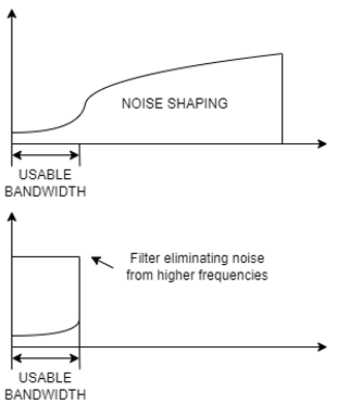
Oversampling is a technique, which uses much higher sampling rate, than it is needed from the standpoint of usable bandwidth. For example, if we are interested in 24 kHz bandwidth 48 kHz sampling frequency is theoretically completely sufficient. However, if we are sampling with 64×48 kHz = 3.072 MHz frequency and we are interested only in frequencies up to 24 kHz it means oversampling by factor of 64. Oversampling paired with specific modulation extends the resolution of DAC. This is why 6-bit DAC with Delta-Sigma modulation is able to achieve 32 bits of effective resolution, as it is with ESS SABRE DACs. Additional benefit of Delta-Sigma modulation is noise shaping. Quantization of analog signal, which makes it possible to digitally represent signal, induces quantization noise. It is because we are encoding only specific levels of signal, and we cannot represent what is between those levels. It is quite intuitive, that more bits result in less quantization noise, because difference between each quantization level is smaller. Therefore, if the DAC itself has 6 bits it should have quite high quantization noise, but because of Delta- Sigma modulation this quantization noise is pushed into higher frequencies, and it is almost non-existent in usable (audio) bandwidth. This effect is called noise shaping (Fig. 1).
Noise shaping is not present in every modulation. PWM (pulse width modulation) does not have this characteristic, although at first sight signals of PWM and Delta-Sigma modulation might look similar. Differences between PWM and Delta-Sigma exceed range of this text.
Main advantage of oversampling DACs is possibility of using lower resolution and higher sampling frequencies because those devices are simpler and more repeatable in production. When combined with oversampling and Delta-Sigma modulation they can surpass non oversampling DACs in effective bit resolution. What is more, there is only need for one analog antialiasing filter (Here this filter is additionally filtering the noise on higher frequencies from Delta-Sigma modulation), which doesn’t have to be tuned and is much simpler. Even when the input sampling rate is changing, only the oversampling factor must change and sampling frequency of DAC itself stays the same. Additionally, because usable bandwidth is many times lower than effective sampling frequency, the slope of the analog antialiasing filter (sometimes also called reconstruction filter) can be much lower, which makes filter much simpler. What is more, this filter can have cutoff frequency much higher, therefore this filter has less impact on signal in audio bandwidth.
Digital filter in oversampling DAC
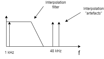
Although oversampling DACs are solving many problems in analog realm, they require more attention at digital side than non-oversampling DACs. Let’s assume, that we want to stream 48 kHz sampling rate file. In the case of oversampling DAC, before signal will be converted to analog form, it must be upsampled from 48 kHz to frequency at which DAC is operating. This operation is called interpolation and that is why digital filters used for this purpose in oversampling DACs are called interpolation filters. However, digital interpolation itself in its simplest form has inconvenient characteristic, which is mirroring signal relatively to old sampling frequency. For example, we have 1 kHz signal sampled with 48 kHz clock. When we will upsample this signal to 96 kHz sampling rate, there will be signals at 48 – 1 = 47 kHz and 48 + 1 = 49 kHz (Fig. 2). This mirroring characteristic is called aliasing and it requires usage of additional digital filter, which will eliminate those aliasing ‘artefacts’, before signal will be applied at DAC input.
However, there is price for using this filter because it has significant impact on the signal in the audio frequencies. There are many factors, which can influence the final sound signature, like slope of the filter, its cut-off frequency, pre- or post-ringing of its impulse response. It is a complicated topic and that is why we are offering many interpolation filters, which have different characteristics for sound signature tuning. Now we have broadened our set of filters by cooperation with expert in that topic.